Showing posts with label Hack. Show all posts

Thursday, November 5, 2015

AUX in Volvo HU-XXXX radio

This post is a description/tutorial on how I managed to hack the stereo (HU-650) in my Volvo V70 (2007) and successfully added my own AUX input. This hack should work with any HU-xxxx unit, "HU" meaning Head Unit (the stereo)


Background

Why, why, why isn't there an AUX input on my car stereo from 2007?
Yes 2007 was before the big era of smartphones, but everyone owned a couple of dirt cheap mp3 players and  iPod was a big thing.

The HU that my car is fitted with has two super retro 8-pin DIN-connections on the back. One of which is for connecting a CD-changer "CD-CHGR" that you could have installed in the boot of the car - but who uses CDs these days?

It didn't take allot of research to find out there is already a product out there that lets you add an AUX to you HU-xxxx. The only drawback is that it sets you back $80 and most of all: It doesn't come with the awesome feeling that you get when you have hacked the stereo yourself.

Research

It wasn't an easy thing finding information on how to hack the HU, but after allot of research I finally found some really good pages that made the hack easy peasy.

This is how it works:

  • The source knob on the HU lacks the ability to choose the CD-CHGR until you connect the CD-changer. 
  • To trick the HU that you have a connected a CD-CHGR is not as easy as to shorten two of the pins on the DIN-connector, but it has to be done in code via a protocol named MELBUS
  • MELBUS is a protocol that utilizes a clock pin and a single bi directional data line to transfer the data between the units and the HU.
  • MELBUS uses three lines: Clock, Data and Busy see blue lines on picture below: ("Run" is just 12V from battery)
Picture source
  • In the picture above you can also see the Left and Right Audio signals that I tapped into for the AUX-input (Red). 
  • Focus on the left DIN-Socket (female) on the picture, that's the back female socket on the HU. 

Hardware


Total cost: ~$3.5

Hacking together some code

Edit 2016-11-04
A guy named Sebastian has modified my code and his version is more stable, and it also works on Mitsubishi HU and supports displaying track numbers! -Here's a link to his code!

Finally some programming! 
I found this awesome write-up that contained almost everything I needed to fool the HU that the Arduino is a CD-CHGR. I will talk you through the process:
  1. Set BUSY to low for 1000 ms to make the HU run its initialization routine
    1. The HU init routine starts by sending three bytes: 0x07 0x1A 0xEE
    2. Then two bytes per optional connection device (~30 of them), the first byte being the predefined ID of the device (ex. CD-CHGR = 0x8E), followed by either an empty byte 0xFF, if the device is not connected, or the answering ID of the device (CD-CHGR = 0xEE)

      Example: External CD-CHGR: ID = 0x8E and its return ID is 0xEE
      Example: Internal CD-player: ID = 0x80 and its return ID is 0x86
      See list of predefined addresses and returns on bottom of this site. 
    3. I.e. to simulate a connected CD-CHGR we have to: 
      1. Trigger the HU init routine
      2. Wait until HU is sending out our ID (0x8E)
      3. Respond to that by sending back 0xEE 
  2. Now the HU has registered that we have a CD-CHGR and it is now available through the source-knob, and will listen to the Left and Right Audio pins on the DIN-plug. 
  3. Every time the car ignition is turned on, the HU will automatically run a secondary initialization routine:
    1. Starting by sending four bytes: 0x00 0x00 0x1C 0xED 
    2. Then two bytes per already registered connection devices from the first init routine, the two bytes follows the same pattern as in the first init routine, first ID, than expecting the same answering byte as before.
    3. If the HU won't get an answer from the CD-CHGR, the device will be removed, and we have to set BUSY low again to call the first init-routine.  
That's it for fooling the HU that the CD-CHGR is connected, now it's just a matter of connecting a device to the Left and Right Audio pins plus Ground. I soldered a network cable plus an 3.5 mm Audio cable to the pins of a DIN-plug.

Take care when reading the schematics above, it is the left socket on the picture you are interested in, that's the socket on the back of the HU-unit (female) and will be equal to the back of the DIN-plug.  (as you can see, I put the red cable on the "RUN" to use the 12V to power the arduino, White and yellow are Audio Left and Right)
As a bonus the 12V is only active when the ignition is turned on => no extra load on battery caused by the arduino when car is not used)


The code I wrote (below) is well documented and fairly easy to understand...

I had a hard time getting the function "SendByteToMelbus(uint8_t byteToSend)" to work.
It turned out that the Arduino functions: digitalWrite(MELBUS_DATA, HIGH); and LOW are too slow for this code, (MELBUS runs at 10-12MHz) and CLK had returned to high state before Databit was changed.

To solve this, I had to go back to the old AVR-GCC technique and use
PORTD |= (1<<MELBUS_DATA); and
PORTD &= ~(1<<MELBUS_DATA);
in place of the Arduino functions.

I tried this setup without any form of ground-loop isolation and it works like a charm! Even when the engine is running and my smartphone is charging through the cigaret-socket the sound is crisp and no disturbing noise (alternator suppose to cause ground noise)

I guess one could buy an external Ground Loop Isolator ($5) to be on the safe side....


Sunday, November 23, 2014

Power Plug Energy Meter - Now wireless!

This is the second post about my work on the cheap China-style energy meter hack.
My last post covered how I with a logic analyzer successfully (but not in the safest way) sniffed the SPI-transmission on the device and managed to decipher the data. And then how I used an Arduino Nano to do the sniffing for me with an interrupt driven approach. The Arduino  translated the bits and bytes to power and voltage values that it continuously printed on the PC's Serial monitor via an USB-cable.

The next obvious step in this project is to get the energy meter to transmit the data wirelessly. Not only would this mean that I could grab data from several energy meters simultaneously, but it also creates a safe way of debugging the device since my previous setup (which I abandoned after reading some of the comments on Hackaday.com) meant connecting the mains neutral to the computers ground (do not try this at home!!!)

Today's post will cover how I managed to get an Arduino pro mini (3.3V) to sniff the energy meters SPI and transmit the data wirelessly with a nRF24L01+ to an Arduino Nano connected to a computer. The neat thing with this setup is that the Arduino pro mini and the nRF fits perfectly within the casing of the energy meter, and are both driven by the internal power that charges the rechargeable battery that you'll find in the meter.


The total cost of components for each energy meter is:
Energy meter             £7.97
Arduino Mini 3.3 V       £2.58
nRF24L01+                 £0.99   (choose the black + version)
A capacitor + cables   pretty much free, say £1

which comes to a total of £12.54 per unit!

Plus one computer connected node, or a raspberry pi with a nRF24L01 to receive the transmissions from all the energy meters.

Arduino and RF24.h
As mentioned in previous blog-posts I have worked quite allot with the nRF24L01 and AVR's, writing my own libraries and so on. But since this is my first Arduino-project I wanted to learn how to import and use other peoples libraries. Since I am still a newbie in programming, I always have to learn everything from scratch, and nothing ever works as supposed to when I try to follow a tutorial...


I started out by setting up two Arduino Nanos according to this guide and running the example code at the bottom of that page, and as expected - it didn't work. 


Debugging
1. Do I have a working SPI-connection?
I had followed the explanation in the guide i linked to above, on how to install the RF24.h-library and it all seamed to work, I definitely had a working SPI-connection between the Arduino and the nRF since I could print out all the registers, and modifying them also worked...

Took me a while to figure out that I had to download and include the file "printf.h" and call "printf_begin();" to print out data from the nRF to the serial monitor... and why, why, why are they using the "protected" attribute  for many of the functions??? For example get_status is a very useful debug-function and should not be protected!

2. Am I using the correct hardware setup? 
As always I hadn't used the exact components as the instructions said, in my drawer I could only find one 47 uF 24 V  and one 100 uF 16 V capacitors. Well in the guide it sais:
"Connect a .3.3 uF to 10 uF (MicroFarad) capacitor directly on the module from +3.3V to Gnd (Watch + and - !) [Some users say 10 uF or more..]"
And I read 10 uF or more....

Anyways, I thought that this should work, since I have used these capacitors before on the nRF, but not with this library and not with Arduino...

3. I found a working code
Yay, suddenly i found a working code, the "pingpair" example that comes with the NRF.h-library worked with my setup!

4. Why does only Pingpair-code work? 
I started stripping the Pingpair-code of its components, and found that my setup was only working when it got into receiving mode in between every transmission... strange, but keeping in mind that I was using bigger capacitors I figured it had something to do with the capacitors not have time enough to recharge/discharge.

I think this is what happened:
When the Arduino calls the "Write" function, the library runs the "startWrite"-function which powers up the nRF and has a predefined delay of 150 us (wait for the nRF to power up) before it starts transmitting the data.
It turned out that this delay was not enough for my setup, so when I changed this to 1000 us (1 ms), the code worked like a charm even without the receiving functions in between! To do this modification, I opened the RF24.cpp-file (in the arduino Sketchbook libraries folder) with notepad, changed the delay, and saved the file.


Arduino Mini
Just as I managed to get a working Arduino code for the nRF, two Arduino Mini 3.3 V landed in my postbox, awesome timing!


One little problem; the Arduino Mini does not come fitted with an USB to Serial-chip to enable programming over USB.... luckily for me I had an USB to Serial adapter laying around (used for debugging AVR's, as I wrote about in this tutorial-post) that I could use to program the Arduino.

Here's a pic of when I have soldered an nRF to the Arduino and uploading code with the USB to COM adapter via a breadboard (out of sight) so the colored cables does not match the pins...


Off course this didn't work straight away either, I found out that when using this kind of FTDI-adapter you have to press the reset-button on the Arduino Mini just when the Arduino-IDE starts to upload the code to get it working! A better buy would be one of these which comes with an automatic reset-pin ("DTR").

I soldered the nRF to the Arduino, and glued them together with some hot-glue, which was also used to attach the unit to the power meter. Plenty of unoccupied room in the meter behind the LCD, and perfect position for a wireless transmitter!


Here you have the wire diagram: 

I started off by just uploading a simple transmission code on the Arduino mini, that would send a dummy byte once a second to confirm a working setup. I  soldered everything together,  plugged the meter into an outlet and kept my fingers crossed as I watched the Arduino-Serial monitor connected to the receiving unit, and.... noting (of course!)

After several hours of debugging, (I thought I had burnt the nRF by hooking it up directly to the power-meters VCC-pin)  It turned out had I accidentally  uploaded a non-working code to the Arduino Mini.... FAIL!!!

I had cleaned up my working code, and shifted some parts around, it seems like you can't open the writing/reading-pipes on the nRF before you set the datarate/payloadsize/PALevel...

Anyway, the setup I found working is grabbing the power directly from the battery (3.6 V soldered to the underside of the PCB) rather than the VCC-cable (which i think is a bit flaky, and is connected to the RAW-pin on the Arduino, which has a built in 3,3 V regulator. I'm not sure this modification is necessary, but it ensures that the nRF and the Arduino gets 3.3 V. (The pictures above are not connected to RAW, but the Arduino's 3.3 V)

Here's whats transmitted to the computer connected Arduino and printed in the Serial monitor:


I have spent some time looking at ways to store and plot this data in the cloud. One interesting approach is to send the data to a website like http://emoncms.org/ and use there ready to use energy-viewing graphs. With the help of a small python-script I wrote, I can easily send the data from my raspberry pi-server to my account on there website where I have the option of making graphs.

I have also been working in the program called "Processing" which is pretty much the same as Arduino-IDE but for graphing and doing stuff with the data.
I have so far programmed a working graph that shows the data output from up to 6 wireless energy meters, it  also logs the data with timestamp to a csv-file. See the processing-code at the bottom.


Above you see a screenshot of when I have plugged in two energy meters (1 and 2). Nr 1 shows a soldering station which i obviously changed the power on allot during the readings. Nr 2 is a 4-step lamp that i flickered from 3 to 0 to 1 to 2 to 3. as you see i didn't stop at 0 for a very long time, so the graphed mean value stopped at ~10W.

You might wounder why the red and green line (nr 1) sometimes differ? That's because I have the meter to transmit the average=red and the maximum=green power readings on every third power reading. This interval is easily changed by typing 1:1 or 1:4 to change the interval on meter 1 from to 1 or to 4 readings in between transmissions.

I had a hard time figuring out how to transmit this new interval from the computer nrf to the meter, because if I in between every transmission changed the nRF to a receiver, the power consumption would cause the whole meter to stop working.

This time I had to do some serious thinking, and I ended up using the possibility to alter the autoAck-payload. A function that normally sends an "OK" from the receiving nrf back to the transmitting nRF to confirm the transmission. I found out how to alter this value to send something like a "2" instead, or some other integer that would be a new interval. This was exactly what I needed, See the code at the bottom!

Her's the working Arduino code, first for the Energy Meter then for the computer connected receiver-Arduino. At the very bottom you have the processing code:


Here's the code for the receiving Arduino (connected to computer via USB)

And finally the Processing code that can be used to read and write to the computer connected Arduino through its serial connection (over USB)

Monday, October 20, 2014

Power Plug Energy Meter Hack

It has been way to long ago since I tested my capability of hacking things.

Since i am an energy engineer, I have been looking for a cheap and easy way of monitoring my power consumption. 
I know there are other hackers out there that have already worked on this problem, and I have seen dozens of hacks on smart and dumb house-power meters, but only a few that covers power plug energy meters. 

You have the Tweetawatt - awesome, but not my cup of tee (i prefer to write my own software for AVR or Arduino) and still ~55$ each...
And a guy named Connor Wolf has an awesome project where he builds his own and a video where he tares a few standard power plug meters apart

I have seen how cheap the China-version of the energy meter is (£7,86), and when i saw the tare-apart video where he takes one apart, I went ahead and ordered two pieces of the EU-type (230V 3,6kW). Of course my intention was to convert them to my own cheaper version of the Tweetawatt.


My final goal is to connect them to the internet either via an nRF24L01+  and my rPi-setup, or with an ESP8266 Wifi adapter (if it will ever arrive in the mail box...)

The future goal is to use an home made Android app to graph the data, i'm not quite there jet, but this tutorial describes how I hacked the power meter and successfully got the voltage, current and power readings to an arduino using interrupts on the CLK. 

The meters showed up last week, and the first thing i did was to open the cover of one of them. 


The guts looked promising since it is very similar to the one in Connor Wolfs video with the 3,6 V battery and the ribbon cable between the two circuit boards. The differences i can see compared to the 110 V version is the big blue capacitor.

The reason I started this project from the first place was because I had seen the ribbon cable labels in the video, so I was very satisfied when I confirmed that the 230 V version also came with the labeled ribbon cable between the power meter and the main processor which sits under the brown circuit board.

The ribbon is labeled: 
VCC, SGND, FREQ, CLK, SDO and SDI as seen here:


I tapped into all of the 7 wires, (7?) yes there are 7 wires, only 6 labeled. closed the case, and plugged it into the wall.

Before i hooked it up to my awesome £6, 8-channel, 24 MHz logic analyzer and started testing it in the logic analysing software, I firs checked all the cables with a multimeter to see that none of them was connected to mains (this video shows that the Kill-a-Watt meter has 110 V on the ribbon cable strangely enough). But the China version was safe on all 7 wires and the five which weren't VCC or GND  got its own channel on the logic analyzer:

###WARNING!!! I'm not an expert in HVAC and there are lots of knowing people that read this article on Hackaday.com and informed me that hooking up the logical analyser like this is an terrible idea! It seems like the energy meters DC-line is not grounded, but instead use Neutral as ground, which can be very different from your computers USB-ground... DO NOT USE MY SETUP, It can be both dangerous and harmful to the computer!

If you want to test the SPI on a non-grounded device they have a lot of suggestions on how this should be done, optical isolation sounds pretty smart (maybe there are even optically isolated USB-hubs you could use?!) I guess I was lucky not to blow up my computer, or my self...


I must admit that this was the first time I have ever attempted to sniff a data communication before, so I had to do a little research. I recognized the CLK as the clock wire in SPI, and guessed that the SDO and SDI was the same as MISO and MOSI but where was the SS (chip select) wire?

My hope was that maybe SPI can work without chip select when there is only one slave that listens, but that would make it heard to know when a transmission starts and end!? how does it sync?

Well, it turns out that I was right, This is the output on a run with nothing connected but the meter:


(click picture for larger version)

Yey, This confirmed my theory and it showed that the FREQ-pin was giving a 50 Hz signal, not at all involved in the SPI communication (nope it's not the SS-line). and that the un-labeled cable was the same as the VCC-labeled pin (high = 3,6V)

This project has improved my analyzing skills allot, and I had to learn how to set up the analyzer to debug the SPI-signal (great SPI-info)

To read this scatter as SPI you need to define the start (where to read the first bit in a byte from)
1. press T1 or hit 1 on keyboard
2. put marker in between SPI-signals (where it's obviously not in the middle of sending a byte)
3-4. Add an Analyzer, choose SPI


Next step is setting up the SPI-analyzer:
1. Press settings
2. zoom in on the first byte, and try and figure out what settings that is used. (see pic under this as well)

Start by "Re-run starting at marker T1" as in picture bellow.
I found that my data is read when CLK is rising "Trailing Edge" and comes in sets of 8 bits (1 byte). 
Note the last MOSI-byte going low, only catched by the trailing edge of clk=>trailing edge
This is how the bits in a byte are interpreted on trailing edge: 


When the CLK goes high, the status on the MOSI and MISO are converted to either 1 or 0. After 8 bits, you have a byte which can be translated to decimal value, as seen above:
MOSI = 1111 1110 => decimal 254
MISO = 0001 0000 => decimal 16

At this time, there was one happy geek in the house!

Decipher the data

Now I had figured out how to sniff the data communication, I still had no idea of what, and in what format the data was sent.

I figured that my best chance of decoding the data would be to sample lots of data and then compare it. So i started sniffing the setup when connecting my soldering station which was perfect since it has the ability to choose different power settings, and for heavy load i used a 1,8 kW water heater.

When comparing the data, it was quite clear that there is not much going on here.The data is sent in chunks of 70 packages at a time, followed by a 47 ms delay. Each package contains 8 bytes, and luckily for me, the first 68 package seems to be the same every time, independent of the wattage reading and they all look like this:

Byte MOSI MISO
1 255 0
2 255 0
3 255 0
4 254 0
5 30 0
6 254 16
7 254 3
8 254 193

Sometimes (under high loads) the 16 reads 80, but that's probably because the 7th bit is misread (i haven't found a pattern):
16 = 0001 0000
80 = 0101 0000

But then in the 68th package it always sends:
ByteMOSIMISO
12550
22550
32550
42540
5300
6254144
72543
8254193

Same thing here, 144 sometimes becomes 280
144 = 1101 0000
208 = 1001 0000

Which i think prepares the Master that next 8-byte package will contain important stuff.
This is what comes out in package 69 with different loads:

ByteSISO 0WSO 8,5WSO 20WSO 44,5WSO 1860W
19400000
21280000
3000000
4000000
52400000
6254115116115115111
725423810231236191
82542498412321518

Which i figured out to be:
Voltage = 2*(Byte6+Byte7/255) 

Which makes sens because when it goes from Byte6=115 and Byte7>238 to Byte6=116 and Byte7=10 It implies a moderate increas in voltage (231,9V=>232,1V), but under high load, one can expect a voltage drop, and when running at 1,86 kW: Byte6=111 and Byte7=191 (223,5V) seems to be correct!

I guess Byte8 represents a very small fractions of voltage level, so i skip that one.

And the last 8-byte package hopefully gives me some sort of current measurement value so that I can calculate the power!?
Package 70 looks like this with different power loads:

ByteSISO 0WSO8,5WSO 20WSO 44,5WSO 1860W
12200000
2254001168
32542162715645
425416811431163243
52000000
6254000014
72540174090137
825425521324870

Where I have tried hard to find out what bit 2 to 4 means, please help me with that in the comment field!!!! The meter displays power factor, could it be something with that?

Anyway, I was luckey, it turned out that the last three bits sends the power value like this:
P=(Byte6*255+Byte7+Byte8/255)/2

And to get the current:
P=U*I means I=P/U  and I have all i need!!!!!

And I am one very happy engineer!

A bonus is that changing the setting to view voltage or current, doesn't change the SPI-data.


Arduino MISO sniffer

I can't have a PC next to every power plug energy meter i have hacked so next step was to program a micro controller to do the SPI-sniffing for me.

I have been using AVR's for quite some time now, but this is my first Arduino project, and for testing purposes I'll be using an Arduino Nano, but I have decided to use an 3,3 V Arduino Mini when it's time to solder everything togeather since I have a 3,3 V battery in the meter, and I am planing on transmitting the read data with either an nRF24L01+ to my rPi-setup, or the ESP8266 Wifi adapter (if it will ever arrive...). I wonder if I need a big fat cap to supply the current when sending data like the Tweetawatt!?

Anyways, my plan is to send the data to Gdrive so that i can reach it from an android app or something, but that's future work! If you read this, and now how to log data from ESP8226 to G-drive or Dropbox, I'd appreciate if you gave me some tips!

I first thought of using the built in SPI-function, but learning how to use the "bitbanging" technic on SPI sounded allot more fun! (and I'm not sure the built in SPI would work anyway without SS)

This is the psudo chode I wrote:
1. Connect GND, CLK (green cable) and SO (blue-white) to Arduino (CLKto INT0 and SO to D5) (Arduino 5V from USB for now)
2. Setup interrupt (ISR) on INT0-pin (D2) and make it trigger on rising edge (se ISR-info)
3. When trigger occures: loop as long as CLK is high while logging the time
4. When CLK goes low: check if the delay was between 1-2ms, if so then we are in clk-sync and next clk-rise will be the start of a new byte (this is the delay in between every one of the 70 packages in a transmission)
5. Let CLK-interrupt trigger 40 times to skip the first 5 bytes of the current package
6. Save status on pin 5 (MISO) every time CLK-interrupt triggers to two integers (the next 8*2 times, which will be Byte6 and 7) by using shifting bits method "<<"
7. Let clk trigger 8 more times to finish a complete package and stay in sync
8. check if Byte7!=3, If true: its the 69th package => use byte 6 and 7 to calculate U and proceed with the next step, otherwise (Byte7==3) then: set sync=false and go back to step 3 and wait/look for next package.
9. Let CLK-interrupt trigger 40 more times to skip the first 5 bytes of the 70th package
10. Save byte 6, 7 and 8 in integers by shifting bits each time a new bit is read (8*3 times).
11. Calculate P and then I=P/U
12. Send U,I,P to computer for debug.


And believe it or not, after a good couple of hours of debugging it now works like a charm!


Here is the code that now sends the data to the Arduino-IDE, but is easily changed to an nRF24L01+ and hopefully the ESP8266  as well...


Update!

I now have a working setup where the energy meter is completely wireless with an Arduino mini pro 3,3V and a nRF24L01+ module! =)
Se next post for further information.
/Kalle

Wednesday, April 3, 2013

Temperature based flow regulator

Since almost none of the readers of this blog understand Swedish, I decided to go international and start writing in English.

In this post I will cover the construction of a temperature based flow regulator that some friends and I have built in order to make sure that the wort temperature is cooled from boiling point to 25°C in our micro brewery. This is important to make sure that the yeast is not killed when added. Since i have some experience in wireless communication we figured it would be cool to make the regulator remotely controlled from an android application.

The setup is kind of similar to my previous project and is built around two Atmega88 with wireless communication through two nRF24L01 adapters (see my tutorial covering the nRF24L01 and AVR).

Regulator setup
- Power supply, 5V 2A USB-power supply (Powerful phone charger that both supplies the Atmega88 and drives the motorized ball valve)

Atmega88, the "computer", a microcontroller that takes and gives commands.

- nRF24L01, 2,4 GHz module that sets up a wireless link with the other nRF-module attached to the computer.

- LM35, Temperature sensor 10mV/°C scale factor and +-0,5°C accuracy.

- Motorized ball valve, 12V (DC-motor works perfectly on 5V, just a bit slower)

- H-bridge, to drive the ball valve DC-motor in ether direction (H-bridge described well here). The components used are two IRF540N (N-channel) and two IRF9540N (P-channel) mosfets.

- Prototype PCB, to solder everything on.

- Heat-exchanger 44kW

- Garden hose connections female, male.


Construction
Armed with a soldering iron, the process went fairly quick and the result is shown below.


The top corner is where the motorized ball valve is connected, and powered via the H-bridge (the fore black mosfets). The temperature probe is attached in the left corner, and the RF-module is the green to the left. The black thing next to the RF-module is a linear regulator that converts the 5 V to 3,3 V since it cannot work with 5 V. When the motor on the valve starts, it produces a huge voltage drop in the system, and therefore it is necessarily to put a large capacitor on the power supply. 


For anyone that wants to construct a H-bridge, i found a great way of soldering them together as you can see at the very top of this picture. Put the two P-channel ones at the back row, and the two n-channel ones in the front row so they line up. Then on each p-channel mosfet you bend the two right connectors (seen from underneath) and solder them to the n-channel ones which you can cut off. For each pair of p+n-channel mosfet you then connect the right rail to respective i/o port on the micro controller, and the middle one to respective DC-motor connection. The  left connectors of the P-channel mosfets connects to 5V, and the left connectors on the N-channel ones connects to ground.


The temperature measurements is done in the hose connector where the wort leaves the heat-exchanger. It looks a bit messy, but at least it does not leak and the quick connector still works! ;)


Setup


The heat exchanger is used as a counter current flow type, and is regulated by controlling the flow of the cold tap-water outlet, so that the temperature of the wort outlet matches its predefined value.


This is an overview of the complete setup of the system (the +-2°C should be -+0,5°C). The home-made module attached to the computer is a similar unit as the regulator, but instead of USB power, temperature probe and dual H-bridge it is connected to the computer via a USB to COM adapter like this one: (i have a small tutorial about USART and Atmega88 here)


Programming

The android application is communication via TCP (wifi or 3G) and is controlled by the same visual basic program i built in the last post to control the ultimate IR-RF remote control:


Screenshots of the android application:


The user can tap on the picture representing the heat exchanger above and set a new temperature for the regulator to aim for. The current temperature is automatically updated every 2 s where it now says "- °C". The two other temperature fields are not up and running at the moment, but in the future they are suppose to regulate the temperature of the boiler and the mash-tun.


If anyone have questions about the build or want me to explain my projects further, please just write a comment!

Thursday, March 21, 2013

Världens nördigaste multifjärrkontroll

Nu har jag äntligen tagit mig tid att sätta ihop vad som antagligen är världens nördigaste multifjärrkontroll!
Det hela började med att jag hackade mina RF-fjärrströmbrytare och mina IR-Fjärrkontroller då jag byggde ihop ett fullt fungerande bibliotek över deras funktioner och hur de sänds.

Tanken med multifjärrkontrollen är att den ska ligga ute i vardagsrummet, där IR-diodena är synliga för stereon, TVn och projektorn och RF-sändaren har bra räckvidd till de flesta rum i lägenheten (den når ca 10m).

Specs Fjärrkontrollen
- Strömförsörjningen till fjärrkontrollen sker via en USB-kabel och en vanlig mobilladdare 5V.

-  nRF20L01 2,4 GHz (en annan modell av RF-sändare än den som pratar med fjärrströmbrytarna). Orsaken till det är att det är väldigt lätt att skicka data mellan två nRF24L01 och de har inbyggda funktioner som t.ex. analyserar om datan mottagits mm.  (se min tutorial som går igenom nRF24L01 ochAVR).

- RF-transmitter 433MhZ för att sätta  på/stänga av fjärrströmbrytarna.

- IR-dioder 2st snodda från gamla fjärrkontroller (ebay) skickar kommandon till stereo, TV & projektor.

- Atmega88 microkontroller - hjärtat i fjärrkontrollen, länken mellan nRF24L01 och övriga komponenter.

Prototypbräda 5x7cm - kretskortet

 Byggnation Fjärrkontroll
Efter nån timme med lödpennan så blev resultatet helt ok faktiskt:


ISP-kontaktena längst hitåt är för att kunna programmera Atmega88'an på plats, och linjärregulatorn till höger om nRF24L01 är för att den kräver 3,3V och resten går på 5V. Transistorn vid IR-diodena är för att jag inte ville bränna chippet då jag parallellkopplar två dioder på samma pinne. Den röda lysdioden längst bort är är bara en indikator som säger när fjärrkontrollen skickar kommandon med antingen IR lr RF (kunde inte hålla mig... ;)

Programvara Fjärrkontroll
Programmet är skrivet i AVR (C-programmering) och gör ingenting fören nRF24L01 mottagit ett packet data, då triggar den en interrupt-pin på Atmega88'an som med hådvaru-SPI läser av de tre byten som mottagits.
Den första byten säger vilken fjärrkontroll som ska simuleras, sedan om det visar sig vara en IR-fjärrkontroll så berättar andra byten vilken knapp som ska tryckas, och om det istället är en RF-fjärrkontroll så säger andra byten vilken fjärrströmbrytare som ska kontrolleras. Tredje och sista byten har endast en funktion om det är en RF-kontroll då den säger om den valda fjärrströmbrytaren ska slås av eller på.

Programmet fungerar mycket bra även utan extern kristall på chippet, så jag antar att timingarna inte är så noggranna när det kommer till IR och RF!


Specs Datorkontrollen
nRF20L01 2,4 GHz - för att trådlöst sända kommandon till fjärrkontrollen

USB-COM adapter för att sända kommandon från datorn till Atmega88 (se min tutorial om hur man får det att funka här)

Atmega88 microkontroller - länken mellan USB-COM adapter och nRF24L01.

Prototypbräda 5x7cm - kretskortet

Byggnation Datorkontroll

Datorkontrollen har jag inte lött ihop ännu, den sitter fortfarande på en test-prototypbräda. Den fungerar iaf så att USB-COM adapterns Tx, Rx och GND är kopplade till Atmega88'ans respektive pinne för att möjliggöra USART-kommunikation.


Programvara Datorkontrollen

Atmega88'an gör ingenting fören ett USART-interrupt går igång då datorn försöker skicka något via COM-porten. Atmegan läser då av de tre byten och skickar de direkt vidare via SPI till nRF24L01-modulen, som då sänder ut det till den mottagande multifjärrkontrollen. Efter lyckad sändning går Atmegan tillbaka till att tom-loopa.


Programvara Datorn
Datorns programvara är ett Windows-baserat VB-program som jag har jobbat på ett tag nu som antagligen ska få ett eget inlägg i bloggen när jag få tid lust och ork, men i stort fungerar den såhär:

Programmer ansluter till önskad COM-port, genom att välja ur listan och trycka på den stora knappen (eller som i mitt fall om har en "Silicon Labs CP210x" så ansluter den automatiskt när programmet startar)
Jag väljer att inte returnera inkommande från COM-porten, annars går programmet in i en oändlig loop eftersom Atmegan är satt att returnera det som skickas till den, och det vill jag inte. Jag väljer också att inte vidarebefordra meddelandet som returneras från atmegan till möjliga TCP-clienter. "StopByte" används för att slippa ange längd på packetet som ska mottas från Atmegan som istället är programmerad att skicka en stopbyte efter varje packet (3 byte data + "#")


Nästa tab är TCP-Servern, och den används för att tillåta inkommande data från internet/wifi. Bara att välja port, och trycka på stora knappen som innan hette "Start". Här vill jag faktiskt vidarebefodra inkommande TCP-data till COM-porten för att på så sätt kunna skicka kommandon från internet direkt till Atmegan. Jag har här valt att returnera inkommande meddelandet till TCP-clienten också, då android-appen är gjord så.


Nu på första tabben, där alla kommandon loggas, samt där man kan skriva kommandon i input text-boxen som i nuläget vidarebefodras till COM-Porten. Här visas också om COM-port är ansluten och om TCP-servern är ansluten och hur många clienter som är anslutna.


De övriga flikarna styr var och om all datakommunikation ska loggas, samt vilka funktioner i programmet som ska autostarta och om hela programmet ska autostarta med windows.


Programvara Android
Vad är väl en multifjärrkontroll om den inte kan styras från multi-enheter... jag satte igång och skapade en android-app som via TCP kan skicka kommandon till fjärrkontrollen:


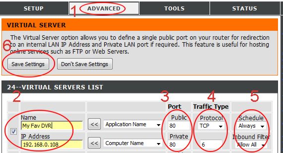
Förstasidan som öppnas är den vänstra, där går man in i TCP-settings och ansluter till rätt IP och Portnr, som jag då sätter till min externa ip-adress för att kunna använda 3G och slippa ansluta till Wifi varje gång jag ska använda appen. Porten jag ansluter till har jag tidigare ställt in i routern såhär så att den forwardar till den rätta porten som ställts in i programmet på datorn.

På förstasidan väljer man sedan att simulera IR eller RF-fjärrkontroller, eller köra förprogrammerade macron där jag bla har ställt in en sekvens som sätter på stereon på AUX, sätter på projektorn och släcker lamporna som sitter på RF-fjärrströmbrytare.

Nästa uppdatering på appen är att man on the fly ska kunna programmera makron som hamnar på de tomma knapparna och sparas. Jag ska också uppdatera datorprogrammet så att det reagerar på vissa kommandon genom att sätta pausa spotify, sätta på XBMC och ändra bildinställningen till projektor-mode.


Om nån vill ha mer info, så skriv en kommentar! =)

Saturday, March 16, 2013

IR fjärrkontroll Hack

Här kommer en redogörelse för hur jag lyckades hacka mina IR-fjärrkontroller som tillsammans med de redan hackade RF-kontrollerna tog mig ett steg närmare den ultimata nörd-fjärrkontrollen ;)

Då jag nu hade tillgång till min logiska analysator var det svårare än att leta reda på de där gamla IR-mottagarna som jag beställt nån gång för länge sen på ebay ;)


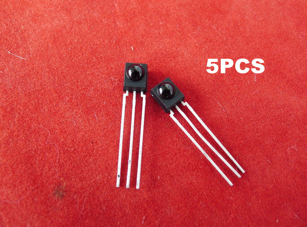
IR-mottagarna är världens simplaste grej! Mata med 5V på högra benet (framifrån), jord på mittenbenet, så kommer vänstra benet vara hög tills en IR-diod lyser på den (lr snarare blinkar på den i 38kHz), då går vänstra benet lågt tills blinkningarna slutar.

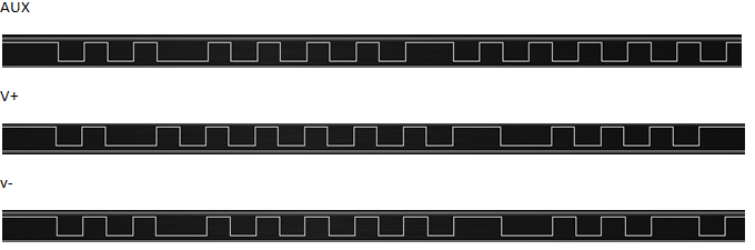
Börja med att ställa in en kanal av den logiska analysatorn på  0 (den börjar spela in när kanalen jordas) och koppla in kanalens probe på vänstra benet av IR-mottagaren, och jord-proben på mitten. Nu är det bara att sikta en fjärrkontroll å skjuta några gånger! Då ser det ut så här:


Lite förstoring på en av signalerna, samt sampling från 3 olika knappar kan se ut så här:


Jag hade tyvärr ingen IR-diod liggandes hemma, så det blev till att offra en gammal fjärrkontroll som ändå inte användes för att kunna testa om jag verkligen lyckats...
Tydligen ska man vara lite försiktig när man kopplar in IR-dioder, de flesta går på lägre än 5v, men den jag hade var 5v!
Ett bra test man kan göra för att inte paja dioden man hittat är att ta upp mobilkameran och rikta den mot en vanlig fjärrkontroll medan man trycker på en av knapparna. En mobilkamera registrerar nämligen IR-ljus som lila-vitt ljus som då syns, lägg märke till hur starkt det är. Gör sedan samma sak med dioden du hittat när du kör ~1,5v, lyser den för lite så testa 3v, å annars se så den inte lyser för starkt på 5v!

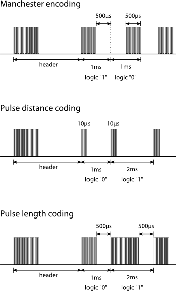
Om man kollar på signalerna ovan, så struntar mottagaren i att skicka ut 38 kHz, utan visar bara konstant jord om den tar emot en ljussigna, eller konstant 5v om den inte... för att mottagaren ska förstå IR-signalen måste koden använda s.k. "manchester encoding" som ser ut så här (timingarna är inte samma på min!):


Nu till det lite kluriga, hur matar jag ut 38 kHz???
Som i tidigare hacks så använder jag mig av en Atmega88, och det visade sig inte vara svårare än att köra vanliga _delay_us(); med 13us på och 13us av, eftersom 1/38000 ~=26us. Noggrannare än så behövdes tydligen inte (inte heller denna gång kör jag med extern kristall, å funkar klockrent ändå)


Funktionen tar in en integer ("i") som bestämmer hur många gånger loopen ska köra, så längden på signalen = 26*i.

Nu var det bara att sätta sig ner och spela in alla fjärrkontroller jag ville ha för att skapa mig ett bibliotek av simulerade knapptryckningar.

Jag har länge stört mig på att vi inte har någon fjärrkontroll till stereon vi har i vardagsrummet som används när vi tittar på film på projektorn, sjukt drygt att resa sig upp å sätta på den eller att gå fram och sänka mm. Så när jag var klar med mitt IR-bibliotek så störde jag mig lite på att den saknades... chalange accepted!!

Jag hade en gammal multifjärr hemma som hade en kod som faktiskt fungerade halvhyffsat på stereon. Dvs tryckte man på en konstig knapp så sattes radion på, och man kunde faktiskt sänka och höja med den, så jag utgick från inspelningarna jag hade av de knapparna (faktiskt de som syns i den inzoomade bilden en bit upp) så jag började med min analys:

1. Självklart började jag med att försöka se ett mönster, och göra smarta gissningar för att hitta rätt kod... jag är ovanligt rik på tålamod, men gav rätt snabbt upp efter att ha sett att alla andra fjärrkontroller inte alls hade nån logik i sig.

2. Nu återstår brutal force ;)

3. Antar att alla signaler börjar med en hög (syns som låg på mottagaren). Det ger 26 höga/låga, vilket är 2^26 = 67108864 möjliga kombinationer aoooo ;(

4. Nu till min revolutionerande upptäckt: tas första biten bort, kommer de ALLTID i antingen låg=>hög, eller hög=>låg, aldrig hög=>hög eller låg=>låg!

Denna upptäckt ger 2^13 = 8192 möjliga kombinationer, vilket är en reducering med 99,987 % =) Har jag dessutom väldigt tur, så gissar jag rätt när jag antar att alla koder börjar på låg=>hög (efter startbiten och ur sändarens perspektiv), då alla tre hittills fungerande koder börjat så. Det skulle isf betyda 2^12 = 4096 olika kombinationer att testa för att hitta rätt =)

Sagt och gjort, jag tillverkade (en mycket smart kod om jag får säga det själv) som loopade igenom de 8192 kombinationerna med 3s mellanrum (märkte rätt snabbt att om jag bara körde med ca 200ms mellanrum så reagerade inte stereon på de värden som de annars brukade (1066 = Vol-)


Så de 8192 kombinationerna tog alltså ca 8192*3/3600 ~=6h, men då jag hade rätt med att allt fanns inom 4096, så tog det bara 3h! =) jag behövde ju inte vara så aktiv, mer än att hålla ett öga på när det hände något, och om det var det jag ville åt så kollade jag vad USARTen rapporterat till datorn! =)

Nu när jag har ett komplett bibliotek med både RF och IR fjärrkontroller är det dags att börja tänka multifjärrarnas multifjärrkontroll!

Om nån vill ha mer info, så skriv en kommentar! =)