

Why use a Raspberry pi when i already have a working TCP-server on my PC?
Easy answered:- I do not like to have my PC up and running 24-7 due to the facts that it's noisy (stationed in my bedroom)
- The RPi takes much less energy (runs on a 1000mA cellphone charger)
- I don't need any other parts other than a RPi, a nRF24L01(+) and cables, since the RPi has a 3,3V power supply!
Setting up SPI on RPi
First of all, you must have a working copy of raspbian, I use Wheezy (made a small tutorial in how to set it up). The RPi has a built in hardware SPI, which we first has to get up and running according to this guide, and here is how i did it:
Start a terminal like the LXTerminal and follow these commands:
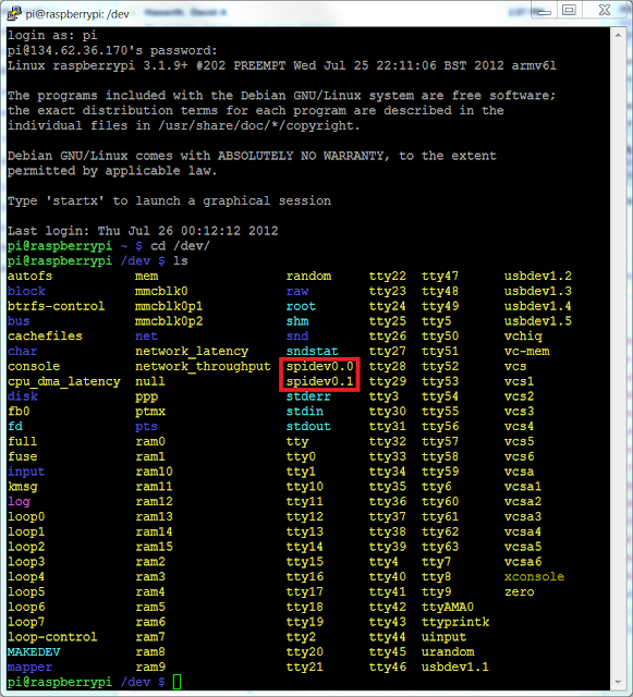
To check if the SPI is working (optional) you can connect the mosi-pin to the miso-pin (GPIO10 and 9, see picture), and run the commands in a terminal:
Start a terminal like the LXTerminal and follow these commands:
To check if the SPI is working (optional) you can connect the mosi-pin to the miso-pin (GPIO10 and 9, see picture), and run the commands in a terminal:


Quick2Wire
Quick2Wire is a tool that makes it possible to control the GPIO and the SPI via python. We need to install quick2wire, download the quick2wire python plugin (API) and gain root access to the spi.
Start by downloading the plugin from there website. Extract the zip-file by right clicking and unzip. Now open a terminal window and change directory so that you are in the extracted folder called "quick2wire-gpio-admin-master" then enter the following commands:
Start by downloading the plugin from there website. Extract the zip-file by right clicking and unzip. Now open a terminal window and change directory so that you are in the extracted folder called "quick2wire-gpio-admin-master" then enter the following commands:
Now log out from the RPi and back in again. The power button at the bottom right quorner has the option to log out. Log back in by typing your username "pi"/enter, then your code "raspberry"/enter...
To gain root access for the SPI so that you dont have to use the "sudo" command in front of every bit of code, I followed this guide, which tells you to do this:
Finnish by remove and reattach the power cable to restart.
Python 3
Now it's time to install python3 which is needed to run the code. Open a terminal and run these commands:Now to use quick2wire with python, you need the python API which can be downloaded from this site. Download it, and unpack it to a location on you SD-card (no installation required!)
Setting up the hardware
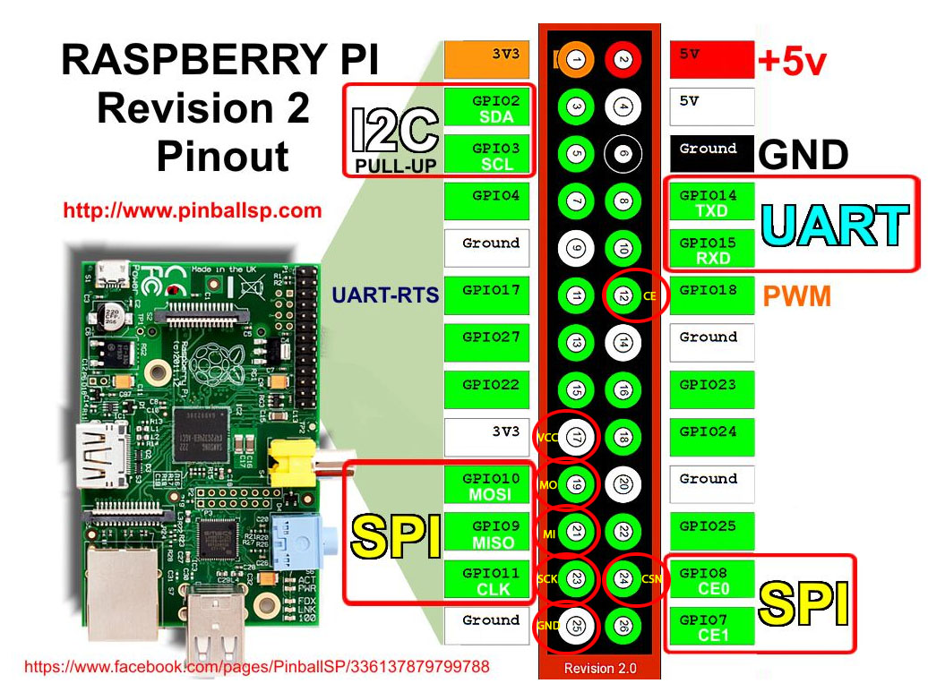
The setup is very straight forward. Connect the wires like this (see red circles in the picture):
RPi GPIO9 (Pin 21) to RF ( MISO )
RPi GPIO10 (Pin 19) to RF ( MOSI )
RPi GPIO11 (Pin 23) to RF ( SCK )
RPi GPIO8 (Pin 24) to RF ( CSN )
RPi GPIO18 (Pin 12) to RF ( CE )
RPI 3.3V (Pin 17) to RF ( VCC/3.3V )
RPi Gnd (Pin 25) to RF (GND)
(IRQ-pin on nRF is not used in this example)
nRF24L02+ (top view)RPi GPIO9 (Pin 21) to RF ( MISO )
RPi GPIO10 (Pin 19) to RF ( MOSI )
RPi GPIO11 (Pin 23) to RF ( SCK )
RPi GPIO8 (Pin 24) to RF ( CSN )
RPi GPIO18 (Pin 12) to RF ( CE )
RPI 3.3V (Pin 17) to RF ( VCC/3.3V )
RPi Gnd (Pin 25) to RF (GND)
(IRQ-pin on nRF is not used in this example)

nRF24L01 (only one of each VCC and GND-pin has to be connected!)

I think the CE-pin should work on a different pin (it would be convenient to put it on GPIO25) since it doesn't have anything to do with the SPI, but I haven't tried that yet...
The python programs
I got the basic nrf python code from this program (plus a lot of help with the steps above) from Jussi Kinnunen, all creds to him!Download my version of the program, as well as my TCP-server program. which is well commented to make it easy to understand. You see the codes below:
nRF24L01p.py
TCP_Server.py
To run the program, create a third file, and name it to something like "a.sh", the ending "sh" means shell file, which is runnable. Fill the file with these commands:
(change the path "/home/pi/" to where you have the quick2wire-folder!)
This will make sure the path is imported every time the script is run! If anyone knows how to permanently add the path, please tell me in the comment field!
To run the program, all you have to do now is to set the working path in the terminal to where you store the a.sh-file with the cd-command and type
This is a screenshot from the code running in the terminal:

As you can see, the program starts by asking if you want to run it as "rx" (Receiver) or "tx" (transmitter). I chose transmitter by typing "tx"/enter.
Then it prints out all the registers that the code changes (or sets) and then starts a server loop in a background thread (TCP).
When this is done the program waits for either the user to type in data to send (3 bytes in my example), or for a command from the TCP-server.
In the picture above, you can see that i started by typing "123" on the keyboard, which was sent to the nRF and broadcasted to any nRF-receiver with address 0x12. As you can see the STATUS register after the broadcast tells me that the transmission failed (0x1E), since i don't have a receiver running at the moment... a working transmission would give the result "0x2E" (when the EN_AA is turned on)!
The second thing I did was to send the command "300" to the TCP-server from my home-made android application (can be sent form any TCP-client with the right port number). The TCP-server then calls the nRF24L01p.py and transmits the data like it was inputted with the keyboard.
If a (large) error shows up when you try to run the code, which tells you something about "cannot export the pin number 18 because it is already exported", run the following command in the terminal:
If an error shoes up that tells you that the address is occupied, the TCP-server has not closed yet, and you have to sit down and wait for up to 1min before you try again (I know you can change this timing, but haven't come so far)
If you have any questions or just want to tell me what you think of the blog, just give me a comment in the comment field underneath...
/Kalle
Hi Kalle,
ReplyDeletethanks for sharing this!
Do you also have a Ardiuno Sketch that sends or listens data to/from the Pi? I already have a working sketch for sending data between two arduinos but I can't get it to work with your python script.
One note about your TCP-Server.py: I'll had to rename it to TCP_Server.py because dashes seems to be forbidden in python syntax.
Best,
Jens
Hi!
DeleteThanks for the note about the names, I have now updated the codes to working names... (my original file names are in Swedish...)
I have a working setup at the moment, where a couple of AVRs (Atmega88 and Attiny26) are connected to nRFs that are in receiving mode, and it is working without problem!
You can see the basics of the code in my previous blog post(http://gizmosnack.blogspot.se/2013/04/tutorial-nrf24l01-and-avr.html), and a code-example (for a AVR-nrf-transmitter) is found on this link: https://gist.github.com/klalle/5652658
Do you have a working SPI-setup between the RPi and the nRF with my python script?
So, SPI is working when I use your test. One thing I noticed is that your screenshot says "STATUS.........[0x0E]" when you start the program and also says "STATUS before..[0x0E]" while mine says "STATUS before..[0x1E]" in both cases. Maybe this is a hint to the problem? Thanks in advance from Hamburg, Jens
ReplyDeleteThe "1" indicates that the "MAX_RT" is set, which is the flag that tells you that maximum number of transmitting retries has occurred. Could it be a problem with the CE-pin? is it connected to the right GPIO (which is set to 0V)? try connecting the CE-pin to GND instead, run the program, and see if it still returns 0x1E!
DeleteI've tested my setup with a C program found on the net. Wiring is the same as for your python script. Got data to and from my arduino, so the hardware side seem ok I think.
ReplyDeleteCould it be a problem with the addresses? For example your code says "ADDRESS=0x12 / SET_RX_ADDR_P0 = [ADDRESS,ADDRESS,ADDRESS,ADDRESS,ADDRESS]" where as my arduino code says "const uint64_t sender_pipe = 0x1212121212LL / write_register(RX_ADDR_P0, reinterpret_cast(&value), 5);".
Does this mean the same?
It must be the same thing, since the code is working on my rpi!
DeleteI have a program that changes the address on the fly, and it certainly works =)
Did you try to ground the CE-pin on the nRF and run the code?
Hi, I see that both of us shared similar interests of nRF24L01, raspberry pi and AVR (Arduino) ... On my blog at almost similar period, I have written on how to get Raspberry Pi, Arduino & attiny85 working on the nRF24L01+ wireless module... and a few more articles on the nRF24L01...
ReplyDeleteWe should exchange knowledge/email and do further improvements to these radios...
http://arduino-for-beginners.blogspot.com/2013/02/setup-nordic-nrf24l01-rf-modules-to.html
I will add your blog to my links so that the blog readers can have more info on these wonderful RF modules.. (hope you also link back to my blog)
Stanley
Hi Stanley!
DeleteNice to see you have found my blog!
I actually started out with you code, but fell in love with the simplicity of the pyton program that Jussi Kinnunen had written...
I will link your blog!
/Kalle
Hi
ReplyDeleteFirst of all, thanks for your help. The tutorial is great.
But my spidev test doesn't give result.
Result:
spi mode: 0
bits per word: 8
max speed: 500000 Hz (500 KHz)
00 00 00 00 00 00
00 00 00 00 00 00
00 00 00 00 00 00
00 00 00 00 00 00
00 00 00 00 00 00
00 00 00 00 00 00
00 00
I just shorted the 2 GPIO Pins mentioned and still... I get 0s as the output. Thanks in advance for your help.
^ Nvr mind.. I got it.
ReplyDeleteBut i have another doubt.
My arduino initially detected it as nrf24L01 after which I corrected my connections and now it shows nrf24L01+.
My raspberry pi now detects my nrf24L01+ module as nrf24L01 and gives
SPI device = /dev/spidev0.0
SPI speed = 8000000
CE GPIO = 25
STATUS = 0xff RX_DR=1 TX_DS=1 MAX_RT=1 RX_P_NO=7 TX_FULL=1
RX_ADDR_P0-1 = 0xffffffffff 0xffffffffff
RX_ADDR_P2-5 = 0xff 0xff 0xff 0xff
TX_ADDR = 0xffffffffff
RX_PW_P0-6 = 0xff 0xff 0xff 0xff 0xff 0xff
EN_AA = 0xff
EN_RXADDR = 0xff
RF_CH = 0xff
RF_SETUP = 0xff
CONFIG = 0xff
DYNPD/FEATURE = 0xff 0xff
Data Rate = 1MBPS
Model = nRF24L01
CRC Length = 16 bits
PA Power = PA_MAX
=> there must be some mistake in connections i made between Raspberry and nrf+ module.
Following is the connecton sequence:
GND to Pin 25
VCC to Pin 17
CE to Pin 24
CSN to Pin 22
SCK to Pin 23
MOSI to Pin 19
MISO to Pin 21
(Above mentioned pin numbers are physical pin numbers)
I feel like there is something wrong with pin22 or may be s
Hi!
DeleteI don't really understand what you are doing there.. I cannot see how your raspberry (or arduino) can detect if you are using the + version or not? And why should that be a problem?
You are clearly not using my bit of python code, and I have seen other codes using other pin configurations, like this for example: http://arduino-for-beginners.blogspot.se/2013/02/setup-nordic-nrf24l01-rf-modules-to.html
good luck with
Great, it worked for me (but nRF24L01.py should be nRF24L01p.py).
ReplyDeleteThanks for the code.
ReplyDeleteI replaced Res == "4E" by Res == "40" to try succeed using it as receiver, which from the datasheet seems normal.
David
Thanks for the notice! I havent actually used the code as a receiver, I just wrote some code that would probably work...
DeleteI still think it is supposed to be "4E"!
The code first checks if ANY flag is set in the status registry (if not "0E"),
then it checks if it is the "RX_DR" (sets high when data arrives) flag, which is bit number 6 in the status registry. We are looking if the status looks like "4E" which equals 0b01001110.
Did you get it working?
Yes, it works with "40" but not with not "4E". It is 0 instead of E since E equals to "111: RX FIFO Empty" but once packet is received this value is the data pipe value "000" in that case.
ReplyDeleteDatasheet says :
("Data pipe number for the payload available for reading from RX_FIFO 000-101: Data Pipe Number 110: Not Used 111: RX FIFO Empty")
Your code was usefull to start my first transmition ;-)
Hi, i'm trying to get it work my Arduino project with your code, but i can't!
ReplyDeleteHere's my Arduino code: http://pastebin.com/c102ENFR
Can you please tell me how to set the settings variables in the .py script to get it work?
I have a C program that works with CE in the pin 24, but i moved my CE pin to 12 but i guess it's not working. I Always receive wrong data conf when i launch the script, and it always print STATUS[0x00] or [0xFF], even though i'm sending nothing.
Please help me. PS, i have rev1 RasPi
Sorry, you will have to bee more specific in your question!
Deleteim very new to the entire scene of electronics and im a bit confused about the communication between the different nRFs, how do you define the address of each node? SET_RX_ADDR_P0 & SET_TX_ADDR ? and if i have more nodes ?
ReplyDeleteWell, there are many different ways to do this!
DeleteIn the example above (see colored code: https://gist.github.com/klalle/5658484) i am just using the P0-channel, and to communicate with different nodes (which I have programmed to the same P0-channel but with different addresses), I could simply call the "changeAddress()" function with the corresponding address to the node i want to communicate with, before I send the data!
The above code is just an example for you to see how you can use the functions i programmed...
If you are using AVR's for the nodes (such as the atmega88 or attiny85), see my other tutorial as well: http://gizmosnack.blogspot.se/2013/04/tutorial-nrf24l01-and-avr.html
DeleteHow do I go about converting the received data to a number, string?
ReplyDeleteFor example I have.
Received.......[0xC7][0x67][0x00][0x00][0x00][0x00][0x00][0x00]
Have you tried google?
Deleteone of the first resault: http://stackoverflow.com/questions/704152/how-can-i-convert-a-character-to-a-integer-in-python-and-viceversa
HELP! I'm getting constant issues with "Permission Denied" referring to the CE pin:
ReplyDeleteTraceback (most recent call last):
File "nrf24l01p.py", line 347, in
SendObj.receiveData()
File "nrf24l01p.py", line 128, in receiveData
self.radio_pin.open() #Open the "CE" GPIO pin for access
File "/home/jherr/projects/gitwork/quick2wire-python-api/quick2wire/gpio.py", line 102, in open
self._file = open(self._pin_path("value"), "r+")
IOError: [Errno 13] Permission denied: '/sys/devices/virtual/gpio/gpio18/value'
It runs fine until my transmitting node actually sends content, then it blows up with that message. I think I did all the steps that would allow for the automated permissions setting, but I could have messed something up. Can you offer me any advice at all?
I'm sorry, I am not a great python programmer, try and google your problem!
DeleteHi , i am new to rapsberry pi and i just bought a b+ model. But could't find any tutorial which show the gpio connection model for b+. Could you please help me on this. Thanks
Deletewith new information. I have found it extremely useful.
ReplyDeletesoundboss car stereo player
MestiQQ Adalah perusahaan judi online KELAS DUNIA ber-grade A
ReplyDeleteSudah saatnya Pencinta POKER Bergabung bersama kami dengan Pemain - Pemain RATING-A
Hanya dengan MINIMAL DEPOSIT RP. 10.000 anda sudah bisa bermain di semua games.
Kini terdapat 8 permainan yang hanya menggunakan 1 User ID & hanya dalam 1 website.
( POKER, DOMINO99, ADU-Q, BANDAR POKER, BANDARQ, CAPSA SUSUN, SAKONG ONLINE, BANDAR66 )
PROSES DEPOSIT DAN WITHDRAWAL CEPAT Dan AMAN TIDAK LEBIH DARI 2 MENIT.
100% tanpa robot, 100% Player VS Player.
Live Chat Online 24 Jam Dan Dilayani Oleh Customer Service Profesional.
Segera DAFTARKAN diri anda dan Coba keberuntungan anda bersama MestiQQ
** Register/Pendaftaran : WWW-MestiQQ-POKER
Jadilah Milionare Sekarang Juga Hanya di MestiQQ ^^
Untuk Informasi lebih lanjut silahkan Hubungi Customer Service kami :
BBM : 2C2EC3A3
WA: +855966531715
SKYPE : mestiqqcom@gmail.com
김해출장샵
ReplyDelete밀양출장샵
사천출장샵
양산출장샵
진주출장샵
창원출장샵
통영출장샵
거제출장샵
익산출장샵
betpark
ReplyDeletetipobet
betmatik
mobil ödeme bahis
poker siteleri
kralbet
slot siteleri
kibris bahis siteleri
bonus veren siteler
J3İBL
Thanks and that i have a neat offer: Whole Home Renovation Cost house renovation mortgage
ReplyDeleteشركة مكافحة حشرات بالجبيل 9roAmvn1um
ReplyDeleteشركة تنظيف مجالس بخميس مشيط rzVtidYYTU
ReplyDeleteصيانة افران الغاز بمكة yxxh3BkCbL
ReplyDeleteشركة تنظيف بالدمام iq7hEjFPl3
ReplyDeleteشركة مكافحة النمل الابيض بالقطيف NtA1tVsPWw
ReplyDeleteشركة عزل أسطح بالقطيف
ReplyDeleteJsGiBwYPiV
شركة تسليك مجاري بعنيزة
ReplyDeleten2ZXvr2uVa
شركة مكافحة النمل بحفر الباطن
ReplyDeletegGGTAMpn0m
شركة تنظيف خزانات ببريدة
ReplyDeleteYG9tmSnn43gj
شركة عزل اسطح وخزانات بالدمام
ReplyDeleteE9g5deLZtxqU
شركة تسليك مجارى بالجبيل
ReplyDeleteCDW9u993oh9pXR